 |
Installing ASRock Motherboard Problems |
Post Reply 
|
| Author | |
parsec 
Moderator Group 
Joined: 04 May 2015 Location: USA Status: Offline Points: 4996 |
 Post Options Post Options
 Thanks(0) Thanks(0)
 Quote Quote  Reply Reply
 Topic: Installing ASRock Motherboard Problems Topic: Installing ASRock Motherboard ProblemsPosted: 28 Dec 2016 at 12:29pm |
|
This picture and description for the System Panel Header from another ASRock board manual should help you. Yes, they are all the same for every ASRock board, since the System Panel Header connections for the PC Case power, reset, power LED, and HDD LED have not changed for PCs in decades:
 Every other mother board connector in the pictures in the manual pages you posted use a single connector with multiple wires/cables that simply plugs into that connector. Some of those connectors are basic and essential (power supply connections), the others are optional, depending upon the other hardware that you may have. Your PSU manual should have instructions about using the connectors it provides, as well as the manuals of all the hardware you may be using in a PC. A mother board is only one of the many components that together make up a PC. We have all had mother boards made by different manufactures, and I don't recall ever seeing a picture/graphic that somehow shows the wires/cables from every possible device in existence is routed to a connector on a mother board. Frankly, a cook book type of connection diagram like that teaches us nothing, and does a disservice to the user. I would never want to be that helpless, requiring a wiring diagram to exist in order to connect the various parts used in a PC. As the description for the System Panel Header states, PC cases may use different connectors, or not include all the connections available on the System Panel Header. For example, your picture did not include the optional power LED connector found on newer ASRock boards, used by some PC case manufactures. Your post brings up a general point that has bothered me for a while now. That is, for some reason, the mother board manufacture is believed to be responsible for explaining how to connect and configure components used in a PC that are not manufactured or sold by the mother board manufacture. For example, does your PC case have a manual that has pictures showing you where to connect all wires it has? The PC cases I use have a manual like that, which I can download from their website. Have you considered using it? If not, why not? Connecting and installing an OS on M.2 PCIe SSDs is the latest example of that trend. Why is the manufacture of the M.2 SSD, and/or the source of the OS software, not seen as the first and foremost source of that information? In reality, as least some of the M.2 PCIe SSD manufactures have that information available, even if it is not included with their products. Yet for some reason, the mother board manufacture, whom has nothing to do with the design and manufacture of M.2 PCIe SSDs, is expected to provide that information. A mother board manual is not meant to be a text book about building a PC. Why would anyone expect it to be? Edited by parsec - 28 Dec 2016 at 12:30pm |
|
 |
|
wardog 
Moderator Group 
Joined: 15 Jul 2015 Status: Offline Points: 6447 |
 Post Options Post Options
 Thanks(0) Thanks(0)
 Quote Quote  Reply Reply
 Posted: 28 Dec 2016 at 9:12am Posted: 28 Dec 2016 at 9:12am |
I beg to differ. In the pics above, the top diagram of pg18, System Panel Header. |
|
 |
|
Palladini 
Newbie 
Joined: 28 Dec 2016 Location: Ontario, Canada Status: Offline Points: 166 |
 Post Options Post Options
 Thanks(0) Thanks(0)
 Quote Quote  Reply Reply
 Posted: 28 Dec 2016 at 8:18am Posted: 28 Dec 2016 at 8:18am |
|
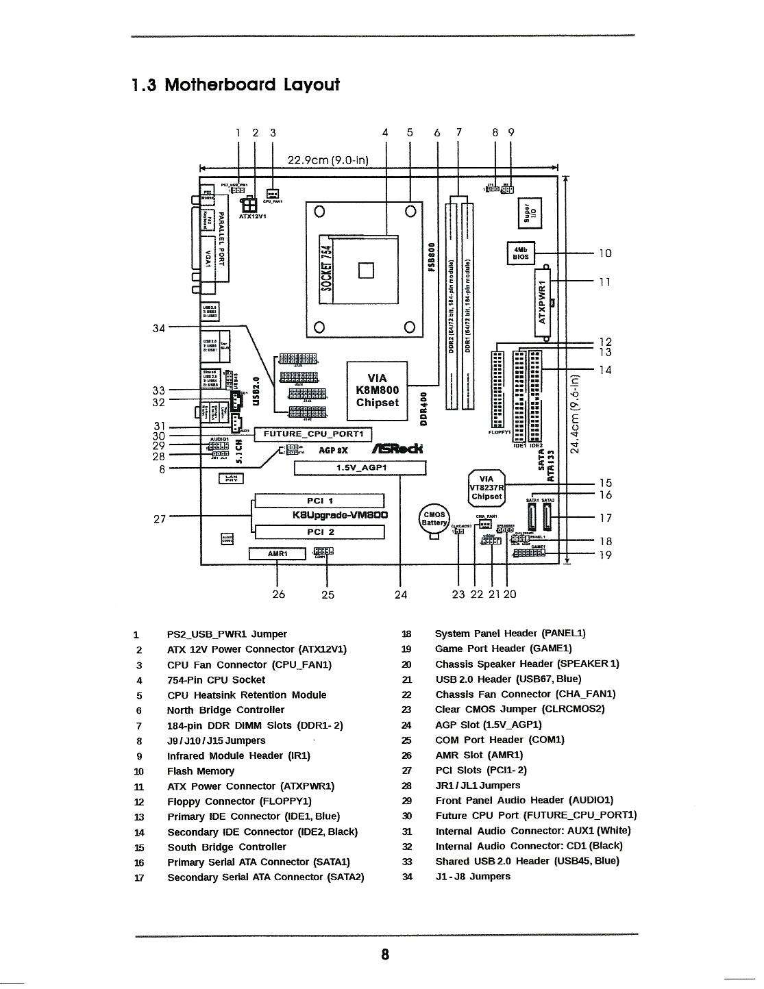
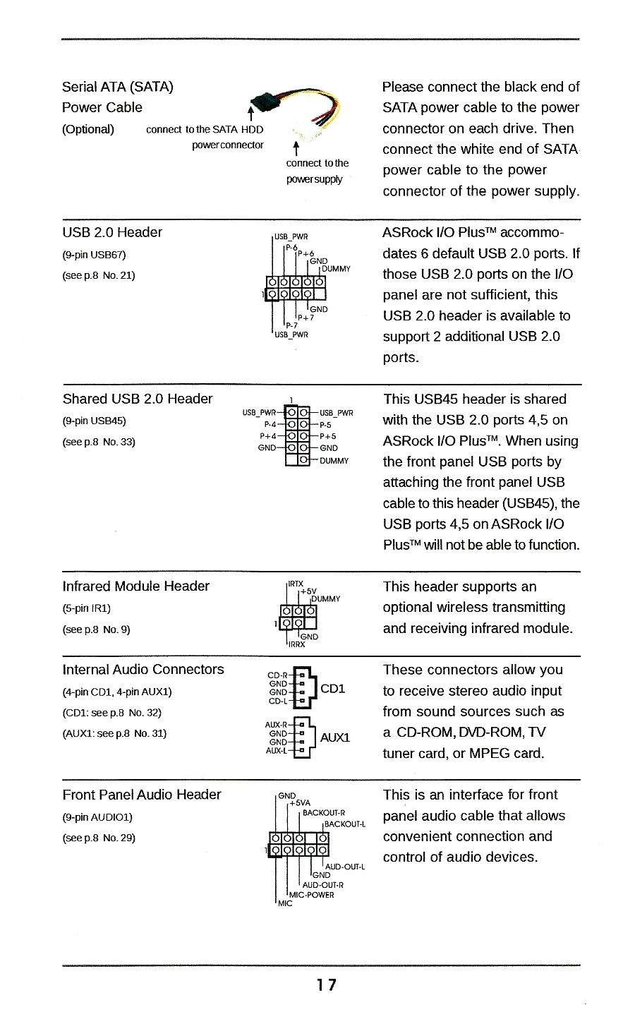
Hello. I have installed an ASRock K8Upgrade - VM800 Motherboard in my case, which is probably newer than the motherboard is. No problem, I only intend to use this as a LAN Storage device or server, it will run Ubuntu. Now here is my problem, I have connected most of the wires in the install, except these ones. from my front panel - 1 - 2 wire power on 1 - 2 wire reset switch 1 - 2 wire HDD LED 1 - Positive single wire Power LED 1 - Negative single wire Power LED    But with these instructions from the PDF, I have no idea where to put any thing. Every other motherboard PDF I have looked at gave you a clear this wire goes here diagram, whereas the ASRock PDF does not |
|
|
Palladini
Video Editor |
|
 |
|
Post Reply 
|
|
|
Tweet
|
| Forum Jump | Forum Permissions  You cannot post new topics in this forum You cannot reply to topics in this forum You cannot delete your posts in this forum You cannot edit your posts in this forum You cannot create polls in this forum You cannot vote in polls in this forum |